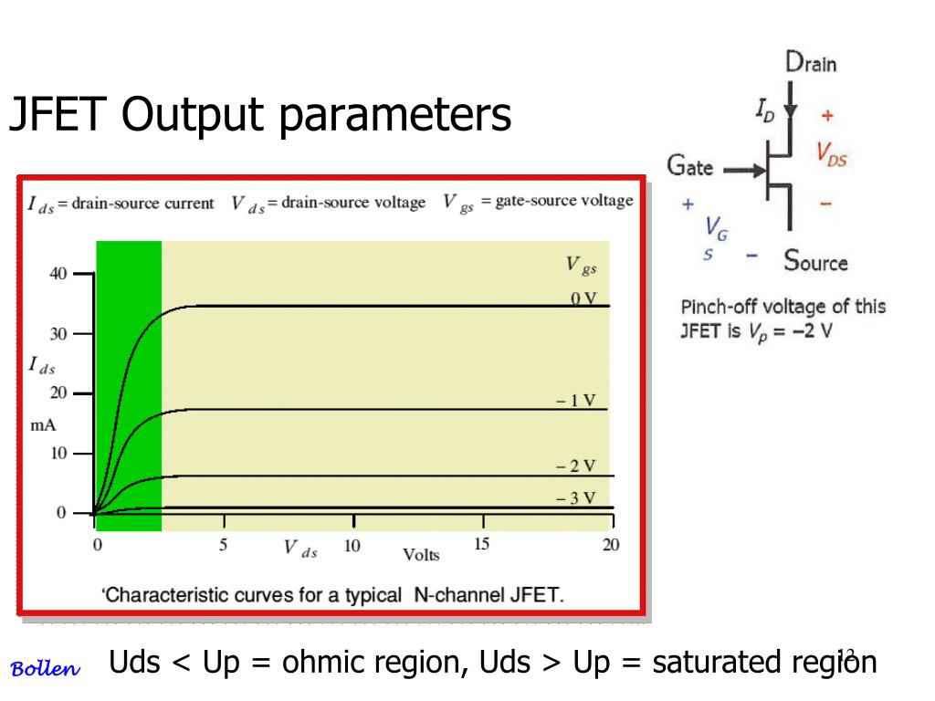

For larger value of VDS, as VDS increases, the depletion layer become wider, causing the resistance of channel increases.Therefore, ID is proportional to VDS for small values of VDS Then, when VDS is increased, ID increases.Water analogy for the JFET control mechanism Holes injected to Source (S) through p-type channel and flowed to Drain (D).Current flow : from Source (S) to Drain (D).Major structure is p-type material (channel) between embedded n-type materialto form 2 p-n junction.Because the resistance of the channel depends on the gate-to-source voltage (VGS), the drain current (ID) is controlled by that voltage.Current flows into the Drain (D), through the channel, and out of the Source (S) In the normal operation of an n-channel device, the Drain (D) is positive with respect to the Source (S).Major structure is n-type material (channel) between embedded p-type materialto form 2 p-n junction.FET is unipolar – uses only one type of current carrier.BJT is bipolar – conduction both hole and electron.Can be fabricated with fewer processing.High input impedance (M)(Linear AC amplifier system).What is the difference between JFET and MOSFET?.JFET (junction field-effect transistor).MOSFET (metal-oxide-semiconductor field-effect transistor).Also used as amplifier and logic switches.Field-effect transistor (FET) are important devices such as BJTs.

CHAPTER 4 :JFET Junction Field Effect Transistor


 0 kommentar(er)
